
T: +86-186-8927-7942
E: kemp@hangjin-machinery.com
E: kemp@hangjin-machinery.com
No. 107 Changning Road, Tongjing Town, Jiangning District, Nanjing, Jiangsu, China
Views: 0 Author: Site Editor Publish Time: 2026-08-13 Origin: Site


In high-volume manufacturing and converting, incorrect blade specification causes excessive material dust, jagged cuts, and frequent machine downtime. These issues usually stem from a single overlooked variable: the micro-mechanics of the cutting edge. Engineers and production managers face a trade-off between initial blade sharpness and long-term edge retention. Selecting an off-the-shelf blade without analyzing the specific interaction between the edge angle, the material substrate, and the machine's cutting force leads to premature blade failure.
Optimizing industrial blade edge geometry transforms cutting from a brute-force operation into a precision mechanical process. This guide breaks down how to evaluate and specify bevels, edge angles, and blade profiles to match specific industrial applications. We will show you how to ensure maximum yield, cutting efficiency, and extended operational lifespans on the factory floor.
Geometry Dictates Performance: The specific angle and bevel configuration of a blade directly determines the cutting force required, the cleanliness of the material separation, and the blade's resistance to wear.
The Sharpness vs. Durability Trade-off: Acute edge angles provide cleaner cuts with less force but are highly susceptible to chipping and rolling; obtuse angles offer durability for abrasive materials but require higher actuation force.
Material-Specific Matching: There is no universal edge geometry. Film converting, paper slitting, and food processing each require distinct bevel profiles (e.g., single, double, compound) to prevent material deformation and machine bog-down.
Table of Contents
Establishing the correct baseline terminology prevents miscommunication when sending technical requirements to custom blade manufacturers. A failure to distinguish between the macro-structure of a machine knife and the micro-structure of its cutting edge results in specifications that look correct on paper but fail under operational stress. Evaluating technical specifications requires a granular understanding of how the edge interacts with the substrate at the exact moment of separation.
The cutting edge is not a single, uniform surface. It is a complex mechanical structure composed of several distinct zones. Each zone plays a specific role in the cutting process. Understanding these zones allows you to pinpoint exactly where a blade is failing and how to adjust the geometry for better performance.
The Apex: This is the exact microscopic point where the two sides of the blade meet to sever the material. The apex handles the initial penetration. A highly refined apex requires less force to break the surface tension of the material, but it remains the most fragile component of the blade.
The Edge Bevel: This represents the ground angle or angles leading directly up to the apex. The bevel dictates the immediate wedge angle that forces the material apart after the apex makes the initial incision.
The Transition Shoulder (Grind Line): Often referred to in specialized tooling as the shinogi line, this is the distinct transition point above the cutting edge where the angle of the blade changes from the primary face to the edge bevel. This shoulder dictates material flow and friction immediately after the cut is initiated. An abrupt shoulder causes material to jam. A smooth transition facilitates continuous slicing.
Thickness Behind the Edge: This metric measures the cross-sectional thickness of the steel immediately above the bevel. It dictates how easily the blade passes through the material after the initial incision. A blade can have a perfectly honed apex, but if the thickness behind the edge is too great, the blade will wedge and bind in the substrate.
A common engineering oversight involves conflating overall blade geometry with edge geometry. Overall blade geometry is task-based. It includes the total length, overall thickness, mounting slots, and general shape. These macro-features are dictated entirely by the machine's design, the mounting apparatus, and the physical constraints of the production line.
Edge geometry is separation geometry. It is the specific micro-profile focused entirely on parting the material and managing the physical forces at the point of contact. You can have two blades with identical task-based geometries designed to fit the same machine, but with entirely different separation geometries tailored for completely different materials.
Comparison: Task-Based vs. Separation Geometry
Feature Category |
Components |
Determining Factor |
Primary Function |
|---|---|---|---|
Task-Based Geometry |
Overall length, width, mounting holes, slot dimensions, base thickness |
Machine make, model, and mounting apparatus |
Securing the blade safely within the machinery and aligning it with the cutting path |
Separation Geometry |
Apex radius, primary bevel angle, micro-bevel angle, transition shoulder |
Material substrate properties (density, abrasiveness, elasticity) |
Initiating the cut, managing friction, and displacing waste material efficiently |
Operators often equate a sharper apex with a superior blade. This misconception leads to significant operational inefficiencies on the factory floor. A blade can possess a razor-sharp, highly polished apex but still fail to cut efficiently if the geometry behind the edge is improperly angled for the substrate. If the transition shoulder is too thick, the machine must exert massive force to push the bulk of the blade through the material. This negates the benefits of the sharp apex. True cutting efficiency relies on the harmonious relationship between the apex refinement and the supporting bevel architecture.
Selecting the correct bevel profile is the most consequential decision in specifying machine knives. The bevel configuration dictates how waste material is displaced, how cutting forces are distributed across the steel, and how long the blade will maintain its structural integrity under continuous operation.
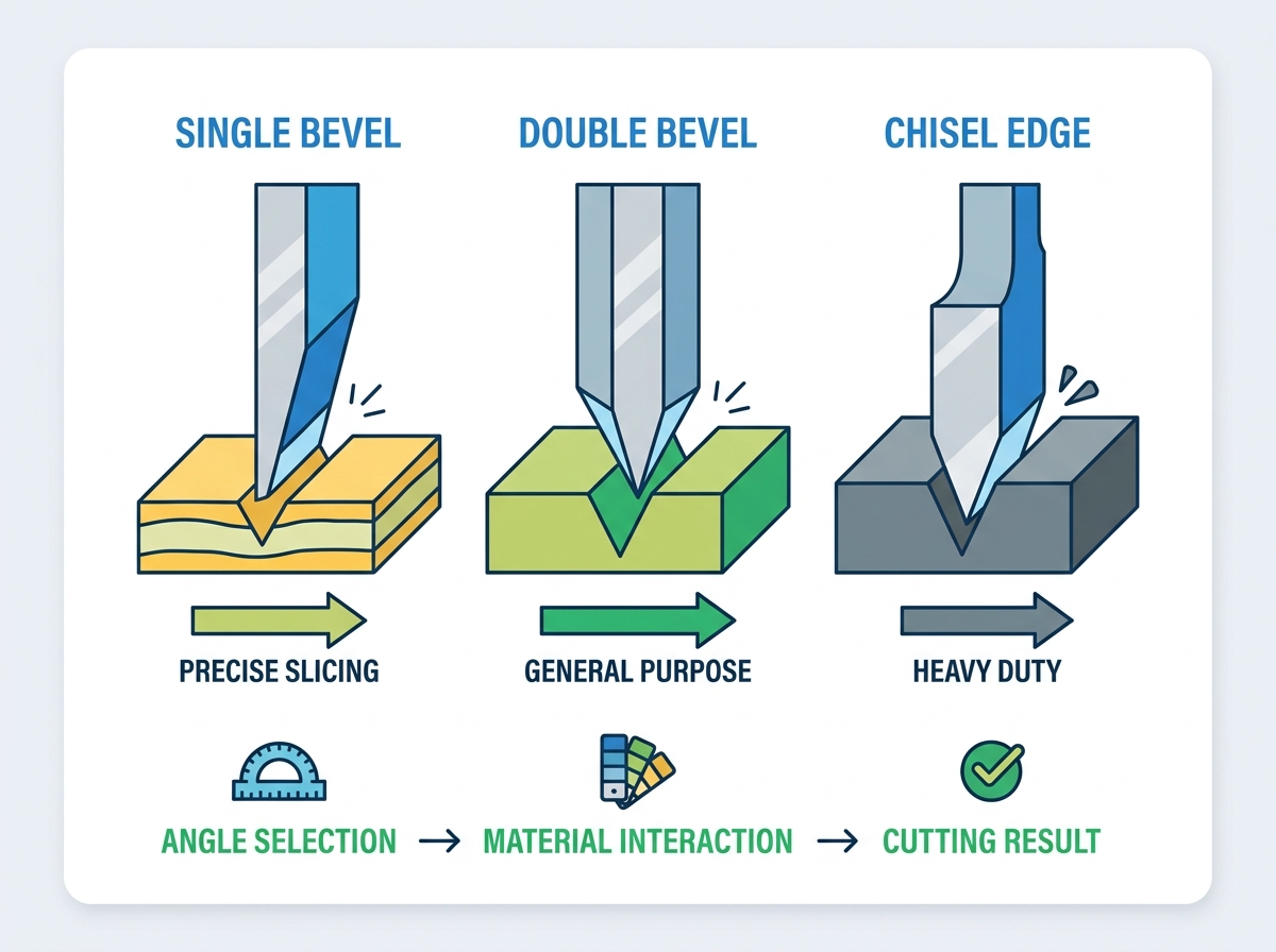
The single bevel profile features a grind on one side of the blade while the opposite side remains completely flat. This asymmetrical design serves a very specific mechanical purpose. It pushes all waste material or offcuts to one side, leaving a perfectly flush, clean cut on the flat side.
Because the flat side creates zero lateral displacement on the retained material, single bevels are heavily utilized in applications requiring strict dimensional accuracy on one half of the cut. Common applications include scraping operations, specialized food processing, and guillotine cutting. The asymmetrical force can cause the blade to drift or steer during deep cuts if the machine lacks sufficient lateral rigidity. You must ensure your blade guides are tightly calibrated when running single bevel knives.
The double bevel, or V-edge, is symmetrically ground on both sides to form the cutting apex. This is the most common configuration for industrial machine knives because it standardizes the cutting force. It pushes material evenly to both sides of the blade. The symmetrical displacement prevents the blade from steering, ensuring straight tracking through thick or continuous substrates.
Double bevels are the standard for general-purpose converting, straight push cuts, slitting, and continuous web processing. The exact angle of the V-edge can be adjusted based on the material, but the symmetrical nature of the grind provides a reliable balance of sharpness and structural stability. When setting up a slitter for standard polyethylene films, a double bevel ensures the web tracks straight without pulling to one side.
A compound bevel involves grinding a primary bevel to thin the blade, followed by a secondary, steeper micro-bevel at the exact apex. This configuration is an engineering compromise designed to combine the low-friction slicing capabilities of a thin blade with the apex strength of a much thicker blade.
The primary bevel reduces the thickness behind the edge, allowing the blade to pass through the material with minimal friction. The steeper micro-bevel reinforces the apex, preventing it from rolling or chipping upon impact. Compound bevels are mandatory for high-impact cutting operations and processing abrasive materials like corrugated cardboard, fiberglass, and reinforced composites. They significantly extend edge life in continuous operations where a simple acute angle would fail prematurely.
Hollow and convex grinds alter the curvature of the bevel itself. A hollow grind features a concave profile, scooping out steel behind the edge to create an extremely thin, friction-reducing geometry. This creates extreme sharpness ideal for delicate slicing, but leaves the apex highly fragile and susceptible to catastrophic damage under lateral stress.
A convex grind features a bevel that rounds outward, putting maximum steel mass directly behind the cutting edge. While not as sharp in terms of initial penetration force, convex grinds offer extreme durability and unparalleled friction management. They excel in heavy chopping applications or when cutting dense, sticky polymers that would otherwise grip and bind a flat-ground blade. In a tire manufacturing plant cutting steel-belted rubber, a convex grind prevents the rubber from clamping onto the blade face.
Industrial Bevel Profile Comparison
Bevel Type |
Profile Characteristics |
Primary Function |
Ideal Applications |
|---|---|---|---|
Single Bevel |
Ground on one side, flat opposite |
Asymmetrical material displacement |
Scraping, guillotine cuts, food portioning |
Double Bevel |
Symmetrical V-shape |
Even force distribution, straight tracking |
Web slitting, general converting |
Compound Bevel |
Primary bevel with steeper micro-bevel |
Combines low friction with high apex strength |
Abrasive materials, high-impact cutting |
Convex Grind |
Outward rounded bevel |
Maximum edge support and friction management |
Dense polymers, heavy chopping |
The mathematical reality of edge angles dictates the physical limits of any cutting operation. Engineers must balance the desire for minimal cutting resistance against the necessity of edge retention. Every degree of angle adjustment changes the distribution of kinetic energy and lateral stress across the microscopic surface of the blade.
Acute angles prioritize penetration and clean separation. By narrowing the wedge angle, the blade requires significantly less mechanical force to initiate and complete the cut. This minimal force requirement prevents the deformation, stretching, or crushing of soft materials prior to separation.
The primary advantage of an acute angle is the maximization of cutting efficiency and edge cleanliness. The physical trade-off is a severe lack of supporting steel behind the apex. Acute edges are highly fragile. When subjected to lateral stress, hard inclusions within the substrate, or slight machine vibrations, the apex is highly susceptible to micro-chipping or edge rolling. They are strictly reserved for materials that offer low resistance and require pristine edge finishes.
Obtuse angles prioritize structural integrity and operational longevity. By widening the wedge angle, more steel supports the apex, allowing the blade to absorb higher impact forces and resist abrasive wear. These angles are engineered to handle dense, hard, or highly abrasive substrates that would instantly destroy an acute edge.
The drawback of obtuse angles is the substantial increase in required machine actuation force. Because the wider wedge displaces material more aggressively, the machinery must push harder to drive the blade through the substrate. If used on delicate materials, obtuse angles tend to crush, tear, or fracture the substrate rather than slicing it cleanly. You will notice immediate web breaks if you attempt to slit thin stretch film with a 30-degree blade.
The bog-down effect occurs when the geometry of the blade creates more friction than the machine's actuators can overcome. This typically happens when an angle is too steep for the material's density, or when a blade is left too thick behind the edge. As the blade penetrates, the substrate exerts compressive force against the primary faces of the bevel.
If the transition shoulder is abrupt or the thickness behind the edge is excessive, this compressive force acts as a brake. The knife wedges tightly into the material, causing the machine to bog down. This leads to immediate machine jams, spiked energy consumption as servo motors strain against the friction, and poor edge quality on the final product. Correcting the industrial blade edge geometry by thinning the primary bevel or smoothing the transition shoulder eliminates this wedging action.
To calculate and prevent the bog-down effect, follow these steps:
Measure the maximum cutting force output of your pneumatic or servo-driven actuators.
Determine the compressive strength and friction coefficient of your target substrate.
Calculate the wedge resistance based on the proposed primary bevel angle.
Ensure the machine's cutting force exceeds the wedge resistance by a minimum safety margin of 20%.
If the resistance is too high, specify a thinner blade stock or a more acute primary bevel.
Applying a universal blade profile across different production lines causes manufacturing defects. The physical properties of the substrate must dictate the specific geometry of the cutting edge. Tensile strength, abrasiveness, cellular structure, and thermal memory all play a role in how the material reacts to the blade.
Flexible materials present a unique challenge. They tend to stretch, warp, or tear before the cut actually initiates. To combat this, the blade must break the surface tension instantly upon contact.
The optimal geometry for films and foils requires extreme sharpness. Acute double bevels, often between 10° and 12° per side, are standard. The bevels are frequently polished to a mirror finish to reduce surface drag. This ensures the film does not stick to the blade face and cause web breaks during high-speed converting. When running BOPP film at 500 meters per minute, a polished 10-degree bevel prevents the material from piling up ahead of the cut.
Paper and cardboard are highly abrasive due to their mineral content, clay coatings, and embedded adhesives. An acute angle will dull rapidly when processing these materials, leading to unacceptable levels of paper dust and jagged edges.
The optimal geometry for these substrates focuses on high wear resistance. Compound bevels or slightly obtuse double bevels (15° to 20° per side) provide the necessary apex strength to maintain edge integrity over millions of cuts. The micro-bevel resists the abrasive wear of the paper fibers while the primary bevel manages the friction of the thicker cardboard substrates. Corrugated board plants rely heavily on compound bevels to keep dust levels manageable.
Food processing requires clean separation without crushing cellular structures. Crushing causes bruising, moisture loss, and accelerated spoilage. The geometry must facilitate easy material release to prevent sticky proteins or starches from building up on the blade.
Single bevels are heavily utilized for portioning, as they prevent the compression of the retained product. Scalloped edges or hollow grinds are frequently employed to reduce the surface area in contact with the food. This minimizes friction and prevents the product from sticking to the knife during rapid slicing operations. Meat processing facilities use hollow ground blades to slice through muscle tissue without tearing the grain.
Cutting dense polymers and rubber generates significant heat due to friction and material memory. As the blade passes through, the rubber compresses and then immediately attempts to expand back to its original shape, gripping the blade tightly.
Friction management is the primary requirement. Convex edges are highly effective here, as the rounded profile parts the material smoothly and prevents the substrate from clamping down flat against the side of the blade. Specialized asymmetrical bevels can also be used to direct the compressive forces away from the cutting path. This reduces heat buildup and prevents the polymer from melting onto the steel.
Substrate to Geometry Matching Matrix
Material Substrate |
Primary Challenge |
Recommended Edge Geometry |
Expected Outcome |
|---|---|---|---|
Stretch Film / Foil |
Stretching before cut initiation |
Acute Double Bevel (10°-12°) with polished face |
Instant penetration, zero web distortion |
Corrugated Cardboard |
High abrasiveness, dust generation |
Compound Bevel (15° primary, 20° micro) |
Extended edge life, reduced particulate dust |
Raw Meat / Produce |
Cellular crushing, product sticking |
Single Bevel or Hollow Grind |
Clean portioning, minimal surface friction |
Dense Rubber / Tires |
Material memory clamping, heat buildup |
Convex Grind |
Smooth parting, prevention of blade binding |
Deploying custom edge geometries on the factory floor introduces specific operational variables. Engineers must anticipate how changes in blade profiles will interact with existing machinery and maintenance protocols to avoid unintended downtime.
When a blade fails before its expected lifespan, the physical condition of the edge provides a diagnostic map of the problem. Reading a failed blade correctly is essential for iterating the geometry. You cannot fix a cutting problem if you misdiagnose the failure mode.
Chipping: Micro-fractures along the apex indicate that the edge angle is too acute for the substrate, or the material contains hard inclusions that exceed the structural limit of the steel. The mitigation is to widen the angle or introduce a compound micro-bevel.
Rolling: If the edge folds over to one side without breaking, the steel is too soft to support the chosen angle under the current lateral load. This requires either a harder steel alloy or a more obtuse angle to increase apex support.
Rapid Dulling: A smooth but quickly rounded apex indicates severe abrasive wear. This requires a geometry change to put more mass behind the edge, or upgrading to a highly wear-resistant carbide or high-speed steel.
A major implementation risk involves upgrading to a thicker, more obtuse blade geometry for durability without verifying the machine's actuation capabilities. Obtuse angles require significantly more force to penetrate materials.
If the pneumatic cylinders or servo-driven actuators cannot deliver the required increased force, the blade will stall mid-cut. Before specifying a wider wedge angle or a convex grind, engineers must calculate the maximum cutting force of the machinery and ensure it exceeds the penetration resistance generated by the new geometry. Do not install a 30-degree blade on a machine rated only for the cutting force of a 15-degree blade.
Compound and convex geometries offer superior performance but introduce significant maintenance challenges. Standard in-house sharpening equipment is typically designed for flat, single, or double bevels. Attempting to resharpen a convex grind or a precise micro-bevel on standard grinding wheels usually ruins the custom geometry. This reverts the blade to a generic, sub-optimal profile.
Facilities must evaluate the trade-off between utilizing complex edge geometry and the logistics of maintaining it. Implementing vendor-managed resharpening programs ensures that the specific angles and transition shoulders are restored to factory specifications. This maintains consistent cutting performance over the life of the blade and prevents operators from destroying expensive custom knives on a bench grinder.
Take the following actions to optimize your cutting operations:
Audit your current blade failure modes by examining discarded knives under magnification to identify chipping, rolling, or abrasive dulling.
Document the exact thickness, density, and abrasive qualities of your primary substrates before ordering replacement knives.
Consult with an industrial blade manufacturer to prototype and test specific bevel and angle configurations tailored to your exact production environment.
Establish a strict resharpening protocol that guarantees the preservation of custom micro-bevels and transition shoulders.
As an industry leader backed by advanced manufacturing technology and decades of expertise in precision knife engineering, Hangjin delivers custom industrial blade solutions designed to exceed rigorous factory tolerances and maximize your operational productivity.
A: Overall blade geometry dictates the shape, total thickness, and mounting style required to fit the machine. Edge geometry focuses strictly on the micro-profile at the apex, including bevels and angles, designed specifically for separating the material and starting the cut efficiently.
A: There is no single universal angle. It depends entirely on the material. Acute angles (10°–15°) are best for soft, flexible films requiring clean cuts. Obtuse angles (20°+) are required for dense, hard, or abrasive materials to prevent edge fracture.
A: A single bevel is ground on one side to push waste away, leaving one perfectly clean edge, which is ideal for scraping or food portioning. A double bevel is ground symmetrically on both sides to form the apex, ensuring straight tracking for general converting and slitting.
A: Geometry dictates how mechanical stress is distributed across the apex and how much friction is generated. Proper geometry minimizes the force needed to slice through materials, reducing actuator strain, preventing heat buildup, and delaying abrasive wear on the steel.
A: Blades bog down when the edge angle is too steep or the thickness behind the edge is too high for the substrate. This creates excessive friction, causing the material's compressive forces to clamp onto the blade, overcoming the machine's driving force.
A: Examine the worn apex. Chipping indicates the angle is too acute or the material is too hard. Edge rolling means the steel is too soft for the chosen angle. Rapid, smooth dulling points to abrasive wear, requiring a geometry adjustment or harder steel alloy.


